Friday, April 25, 2014

Modify Multilines

Modify Multilines

Multiline objects are composed of 1 to 16 parallel lines, called elements. To modify multilines or their elements, you can use common editing commands, a multiline editing command, and multiline styles.
Special multiline editing features are available with the MLEDITcommand including the following:
  • Add or delete a vertex
  • Control the visibility of corner joints
  • Control the style of intersection with other multilines
  • Open or close gaps in a multiline object 

Add and Delete Multiline Vertices  

You can add or delete any vertex in a multiline.


Edit Multiline Intersections  

If you have two multilines in a drawing, you can control the way they intersect. Multilines can intersect in a cross or a T shape, and the crosses or T shapes can be closed, open, or merged.

 Edit Multiline Styles 


 You can use MLSTYLE to edit multiline styles to change the properties of multiline elements or the end caps and background fill of subsequently created multilines.
Multiline styles control the number of line elements in a multiline and the color, linetype, lineweight, and offset of each element. You can also modify the display of joints, end caps, and background fill.
Multiline styles have the following limitations:
  • You cannot edit the element and multiline properties of the STANDARD multiline style or any multiline style already used in the drawing.
  • To edit an existing multiline style, you must do so before you draw any multilines in that style.
NoteIf you use MLSTYLE to create a multiline style without saving it, and then select another style or create a new style, the first MLSTYLE properties are lost. To maintain the properties, save each multiline style to an MLN file before creating a new one. 


Use Common Editing Commands on Multilines 


You can use most of the common editing commands on multilines except
  • BREAK
  • CHAMFER
  • FILLET
  • LENGTHEN
  • OFFSET
To perform these operations, first use EXPLODE to replace the multiline object with separate line objects.
NoteIf you trim or extend a multiline object, only the first boundary object encountered determines the shape of the end of the multiline. A multiline cannot have a complex boundary at its endpoint. 


To delete a vertex from a multiline
  1. Click Modify menu ObjectMultiline.
  2. In the Multiline Edit Tools dialog box, select Delete Vertex.
  3. In the drawing, specify the vertex to delete. Press Enter.
To create a closed cross intersection
  1. Click Modify menu ObjectMultiline.
  2. In the Multiline Edit Tools dialog box, select Closed Cross.
  3. Select the multiline for the foreground.
  4. Select the multiline for the background. The intersection is modified. You can continue selecting intersecting multilines to modify, or press Enter to end the command. Press Enter again to redisplay the Multiline Edit Tools dialog box.
To edit a multiline style
  1. Click Format menu Multiline Style.
  2. In the Multiline Styles dialog box, select the style name from the list. Click Modify.
  3. Click Element Properties.
  4. In the Modify Multiline Styles dialog box, change the settings as needed.
  5. Click OK.
  6. In the Multiline Styles dialog box, click Save to save the changes to the style in the MLN file.
  7. Click OK.
Commands
MLEDIT
Edits multiline intersections, breaks, and vertices.
MLSTYLE
Creates, modifies, and manages multiline styles.
 

Draw Multiline Objects

Draw Multiline Objects

Multilines are composed of 1 to 16 parallel lines, called elements.
When you draw a multiline, you can use the STANDARD style, which has two elements, or specify a style that you created previously. You can also change the justification and scale of the multiline before you draw it.
Multiline justification determines which side of the cursor that the multiline is drawn, or whether it is centered on the cursor.
Multiline scale controls the overall width of the multiline using the current units. Multiline scale does not affect linetype scale. If you change the multiline scale, you might need to make equivalent changes to the linetype scale to prevent dots or dashes from being disproportionately sized.


Create Multiline Styles 

You can create named styles for multilines to control the number of elements and the properties of each element. The properties of multilines include
  • The total number of elements and position of each element
  • The offset distance for each element from the middle of the multiline
  • The color and linetype of each element
  • The visibility of the lines, called joints, that appear at each vertex
  • The type of end caps that are used
  • The background fill color of the multiline

You can add up to 16 elements to a multiline style. Elements with a positive offset appear on one side of the middle of the multiline; elements with a negative offset appear on the other side of the middle of the multiline.


To draw a multiline
  1. Click Draw menu  Multiline.
  2. At the command prompt, enter st to select a style.
  3. To list available styles, enter the style name or enter ?.
  4. To justify the multiline, enter j and select top, zero, or bottom justification.
  5. To change the scale of the multiline, enter s and enter a new scale. Now draw the multiline.
  6. Specify the starting point.
  7. Specify a second point.
  8. Specify additional points, or press ENTER. If you specify three or more points, you can enter c to close the multiline.
To create a multiline style
  1. Click Format menu  Multiline Style.

  2. In the Multiline Style dialog box, click New.
  3. In the Create New Multiline Style dialog box, enter a name for the multiline style and select a multiline style from which to start. Click Continue.

  4. In the New Multiline Style dialog box, select the parameters for the multiline style. You can also enter a description. Descriptions are optional and can be up to 255 characters, including spaces.

  5. Click OK.
  6. In the Multiline Style dialog box, click Save to save the multiline style to a file (the default is acad.mln). You can save multiline styles to the same file. If you create more than one multiline style, save the current style before creating a new one or you lose the changes to the first style.


Commands
OFFSET
Creates concentric circles, parallel lines, and parallel curves.
MLINE
Creates multiple parallel lines.
MLSTYLE
Creates, modifies, and manages multiline styles.
System Variables
CMLSTYLE
Sets the multiline style that governs the appearance of the multiline.

Quick Access Toolbar

                                                        Quick Access Toolbar

Display frequently used tools with the Quick Access toolbar.


View Undo and Redo History

The Quick Access toolbar displays options to undo and redo changes to your file. To undo or redo a less recent change, click the drop-down button to the right of the Undo and Redo buttons.


Add Commands and Controls

Add unlimited tools to the Quick Access toolbar. Tools that extend past the maximum length of the toolbar are displayed in a flyout button.
To add a ribbon button to the Quick Access toolbar, right-click the button on the ribbon and click Add to Quick Access toolbar. Buttons are added to the right of the default commands on the Quick Access toolbar.

 Move the Quick Access Toolbar

Place the Quick Access toolbar either above or below the ribbon using the Customization button.

To add a command to the Quick Access toolbar
  1. Right-click the Quick Access toolbar.
  2. Click Customize Quick Access Toolbar.
  3. In the Customize User Interface (CUI) Editor, drag a command from the Command list to the position you want it to be displayed on the Quick Access toolbar. For multiple commands, hold down CTRL and select the commands.
  4. Click OK.
    NoteIf you do not click OK, the commands added are not saved to the Quick Access toolbar.
To remove a command from the Quick Access toolbar
  1. Right-click over the command you want to remove.
  2. Click Remove from Quick Access Toolbar.
Commands
CUI
Manages the customized user interface elements in the product.

Create Annotative Blocks and Attributes

                                  Create Annotative Blocks and Attributes
Commands
ATTDEF
Creates an attribute definition for storing data in a block.
BLOCK
Creates a block definition from selected objects.
System Variables
ANNOTATIVEDWG
Specifies whether or not the drawing will behave as an annotative block when inserted into another drawing.
=============================
To create an annotative block definition
  1. Click Blocks & References tabBlock panelCreate.
  2. In the Block Definition dialog box, enter a block name in the Name box.
  3. Under Objects, select Convert to Block.
  4. Click Select Objects.
  5. Under Behavior, select Annotative.
  6. Use your pointing device to select objects to be included in block definition. Press ENTER to complete object selection.
  7. In the Block Definition dialog box, under Base Point, specify the block insertion point.
  8. Click OK. 
#   To update existing block references to be annotative
  1. Click Blocks & References tabBlock panelCreate.
  2. In the Block Definition dialog box, Name box, click the arrow and select the name of the block you want to update to be annotative.
  3. Under Behavior, select Annotative.
  4. Click OK. The existing block references in the drawing are now annotative.
  
To create an annotative attribute definition
  1. Click Blocks & References tabAttributes panelDefine Attributes.
  2. In the Attribute Definition dialog box, set the Attribute Modes and enter Tag information, Insertion Point and Text Settings.
  3. Under Text Settings, select Annotative.
  4. Click OK.
  5. Specify the start point.
  6. Press ENTER.
If you want to use geometric objects to annotate your drawing, combine the objects into an annotative block definition.
Annotative block definitions create annotative block references. Annotative block references and attributes initially support the current annotation scale at the time they are inserted. You should insert annotative block references with a unit factor of 1.

Wednesday, March 27, 2013

Troubleshoot a Stand-Alone License Error

When you activate your Autodesk product, only the computer that you used to activate the product is licensed to run the product. If you make certain changes to your computer, your stand-alone license might fail. You will receive a license error and you will not be able to use your product. This section discusses ways in which you can troubleshoot a license error. Some license errors require you to reactivate your product. If you need to reactivate your product, the Product Activation wizard is displayed when you try to run the product. To reactivate your product, follow the instructions in the Product Activation wizard. The following topics offer more details regarding specific errors.

Hardware Changes

If you replace or reconfigure hardware on the computer where your Autodesk product license resides, the stand-alone license might fail. You will not be able to use your product. To prevent damage to your product license, use the License Transfer Utility to export your license file. After you make the hardware change, you can import the license file back. For instructions about using the License Transfer Utility, see Transfer Your Stand-Alone License on page 5.

NOTE If you get a license error when you change your hardware, you may have
to reactivate your license. See Activate Your Product on page 2.

Reinstalling an Operating System

If you reinstall your operating system on the computer where your Autodesk license resides, the license might fail. You will not be able to use your product. To resolve a license error in this case, you must reactivate your product. See Activate Your Product on page 2. To prevent a license error when you reinstall an operating system

NOTE If using Norton Ghost™ or another image utility, do not include the Master Boot Record.

1 Locate one of the following folders and make a backup copy:
■ (Windows XP) C:\Documents And Settings\All Users\Application
Data\FLEXnet
■ (Windows 7/Windows Vista) C:\ProgramData\FLEXnet
2 Reinstall the operating system and reinstall the Autodesk product.
3 Paste the license folder to the same location from which you originally
copied the folder in step 1.
You can now run your Autodesk product.

Changing the System Date and Time

Your product license allows for time changes to the system clock within two days of the current time. If you set your system clock back more than two days, the next time you start your product, you will receive a message that gives you the option of correcting the system clock. If you do not correct the system clock, you receive a license error.
To prevent a license error due to a change in system date and time

■ Make sure that your computer's system date and time are accurate when
you install and activate your Autodesk product.

Distributing Software Image to Multiple Computers


You can use the Deployment Wizard’s Stand-alone option to create a software installation image on your server. You can distribute this image by making it available on your computer network. During creation of this image, you are prompted for registration information, which is stored with the image and deployed to all installations. Additionally, you can manually distribute the software using the installation CD that comes with your Autodesk product. However, if your computers do not have an Internet connection, make sure the registration data for each computer matches exactly. Inconsistent registration data can cause activation
failures.

To prevent a license error when distributing software image to multiple computers

■ The distribution of applications using “ghosting” is not recommended, and can result in incomplete installations and activation problems.

Preserving Licenses on Re-Imaged Computers:


On a network license server, licenses are maintained on the server. No additional steps are needed to preserve network licenses. For stand-alone licenses, you need to export the licenses to a safe place before
re-imaging the computers. You can use the License Transfer Utility to export the licenses. After the re-imaging, import the licenses to the correct computer. Each license only works on the computer for which it was created.


How to use - AutoCAD License Transfer Utility


            Using the AutoCAD License Transfer Utility
The License Transfer Utility transfers a product license online from one computer to another, and ensures that the product works only on the computer that contains the license. The License Transfer Utility is a custom stand-alone installation option. During installation, a shortcut is created. A shortcut is installed once per product, per workstation. You may want to transfer a license to a computer temporarily (if you want to use an Autodesk product on your laptop, for example) or permanently (if the computer where you originally activated your Autodesk product is being replaced). You can leave the license on the secondary computer indefinitely, or you can move the license between computers as needed. License transfers rely on the product’s serial number. Before an Autodesk product can be exported, it must be activated with the serial number and product key. During license import, a previously activated and exported license is imported to a product or product suite installed with the same serial number. The activation is transferred to the import computer, completing the license transfer.

Exporting a license
The first step is to launch the LTU. It's on the Start Menu in the same program group as your application. The initial dialog will look like this

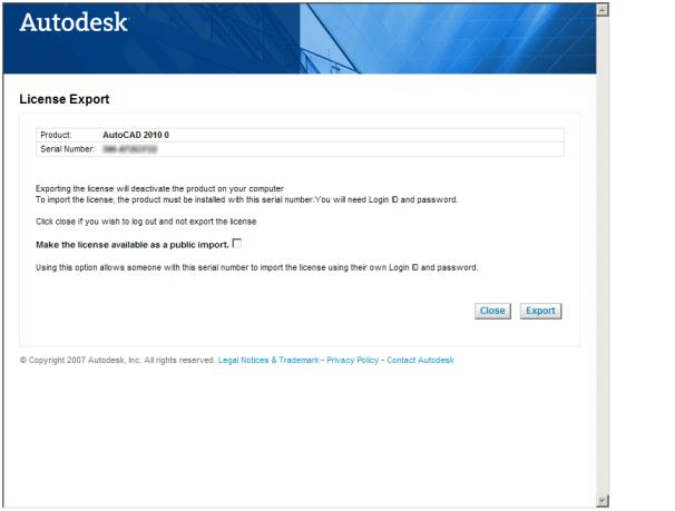
Click the Sign In button. After you have signed in (or created a new account and signed in), the next dialog will look like this:


                                                                                                                                                                         By default, you will only be able to import this license to a machine with the same serial number and the same Autodesk account. If you check the "Make the license available as a public import", then anyone can import the license. The AutoCAD install will still need to be done with the same serial number as the install from which the license was exported.

This next screen is confirming that the license was exported successfully.
Importing a license
Now you are ready to import on a different machine. Remember, the second install must use the same serial number. Start the same application (LTU) on the second machine, and after you log in, the license importing process will begin.
 
 
After this has completed, a confirmation dialog will appear letting you know that the license was imported successfully. 


Another ways:-


Export a License
1. A license is exported when the License Transfer Utility moves a product license from a computer to the online Autodesk server.

2.  The license can be exported as public or private. Exporting a license as public means that you are not reserving the license and anyone using the same serial number and their own user ID and password can import that license. Exporting a license as private means that you are reserving that license for yourself and the license can only be imported with the same serial number, your user ID, and your password.

NOTE An Internet connection is required to export a license.

To export a license

1 On the computer where you want to export the license, do the following:
(Windows XP/Windows 7/Windows Vista) Click Start All Programs
Autodesk [Autodesk Product] License Transfer Utility.
1. The Export the License dialog box displays the Autodesk product name and serial number.
2 In the Export the License dialog box, click Sign In.
3 On the Log In page enter your Autodesk user ID and password and click
Log In.

4 On the License Export page, confirm the export information.

5 If you want to make the license available as a public import, click Make
the license available as a public import.

6 Click Export.

7 On the License Export Confirmation page, click Finish.


Import a License

A license is imported when the License Transfer Utility moves a previously exported product license from the online Autodesk server to a computer. When you have exported a product license from a computer, you complete the license transfer process by importing that license onto a computer. A license is imported when the License Transfer Utility creates an active license on a computer, allowing your Autodesk product to run on this computer. When you use the License Transfer Utility to import a license to a computer, you are not activating the product on the computer; you are simply transferring your activation to this machine.

NOTE An Internet connection is required to import a license.


To import a license
1 On the computer where you want to import the license, do the following:
(Windows XP/Windows 7/Windows Vista) Click Start All Programs
Autodesk [Autodesk Product] License Transfer Utility. The Import the License dialog box displays the Autodesk product name and serial number.

2.  In the Import the License dialog box, click Sign In.
3.  On the Log In page, enter your Autodesk user ID and password and click Log In.
4. On the License Import Confirmation page, click Finish.

The license is now imported to the computer and you can run your Autodesk product on this computer. If you want to transfer the license to another computer, repeat the export and import procedures. To import a license to replace a trial license

1.  On the computer where you want to import the license, do the following:
(Windows XP/Windows 7/Windows Vista) Click Start All Programs
Autodesk [Autodesk Product] License Transfer Utility.
1. The Update the Serial Number and Product Key dialog box displays the Autodesk product name and serial number.
2.  In the Update the Serial Number and Product Key dialog box, enter the serial number and product key to update your Autodesk product. Click Update. The Import the License dialog box displays the Autodesk product name and updated serial number.
3. In the Import the License dialog box, click Sign In.
4. On the Log In page, enter your Autodesk user ID and password and click Log In.
5. On the License Import Confirmation page, click Finish.

The license is now imported to the computer and you can run your Autodesk product on this computer. If you want to transfer the license to another computer, repeat the export and import procedures.